标签: ELC220

物理代写|光电技术代写Photovoltaic Technology代考|EGV2101

如果你也在 怎样代写光电技术Photovoltaic Technology这个学科遇到相关的难题,请随时右上角联系我们的24/7代写客服。

光伏材料和装置将太阳光转化为电能。一个单一的光伏设备被称为电池。

statistics-lab™ 为您的留学生涯保驾护航 在代写光电技术Photovoltaic Technology方面已经树立了自己的口碑, 保证靠谱, 高质且原创的统计Statistics代写服务。我们的专家在代写光电技术Photovoltaic Technology代写方面经验极为丰富,各种代写光电技术Photovoltaic Technology相关的作业也就用不着说。

我们提供的光电技术Photovoltaic Technology及其相关学科的代写,服务范围广, 其中包括但不限于:

  • Statistical Inference 统计推断
  • Statistical Computing 统计计算
  • Advanced Probability Theory 高等概率论
  • Advanced Mathematical Statistics 高等数理统计学
  • (Generalized) Linear Models 广义线性模型
  • Statistical Machine Learning 统计机器学习
  • Longitudinal Data Analysis 纵向数据分析
  • Foundations of Data Science 数据科学基础
物理代写|光电技术代写Photovoltaic Technology代考|EGV2101

物理代写|光电技术代写Photovoltaic Technology代考|Common-Mode Behavior

The transformerless technology offers high-efficiency PV inverter at reduced cost. This explained why the PV inverter trend is moving toward transformerless topology. In order to understand the fundamental principle of the transformerless topology, the common-mode behavior will be analyzed here based on single-phase system. The similar common-mode behavior analysis can be extended to three-phase system, and thus the three-phase analysis will not be covered here.
When the transformer is removed from PV inverter, galvanic connection is formed between the PV arrays and the grid. This galvanic connection creates a leakage current path as shown in Fig. 12. When the CMV is produced by the inverter topology with corresponding pulse width modulation (PWM), the CMV charges and discharges the stray capacitance. As a result, leakage current is generated, flowing through the leakage current path between the PV arrays and the grid. In order to design a suitable transformerless PV inverter topology with reduced leakage current, the common-mode behavior must first be understood. A common-mode model circuit is derived here and simplified stage by stage to study the common-mode behavior of the transformerless PV inverter.

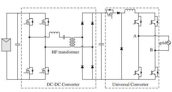
For transformerless inverter, a resonant circuit is formed as shown in Fig. $13 .$ This resonant circuit includes the parasitic capacitance $\left(C_{\mathrm{PV}}\right)$, the filter inductors $\left(L_1\right.$ and $L_2$ ), leakage current $\left(I_L\right)$. Here, the power converter is represented by a block with four terminals to allow a general representation of various converter topologies. On the DC side, $P$ and $N$ are connected to the positive and negative terminal of the DC link respectively; while on the $\mathrm{AC}$ side, terminals $\mathrm{A}$ and $\mathrm{B}$ are connected to the single-phase grid via filter inductors [15].

From the view of point of grid, the power converter block as shown in Fig. 14 can be considered as voltage sources, generating into equivalent circuit which consists of $V_{\mathrm{AN}}$ and $V_{\mathrm{BN}}$. Obviously, the leakage current is a function of $V_{\mathrm{AN}}, V_{\mathrm{BN}}$, grid voltage, $L$ and $C_{\mathrm{PV}}$. Since the grid is a low-frequency voltage source ( 50 or $60 \mathrm{~Hz}$ ), the impact on the common-mode model will be ignored here. Therefore, a simplified common-mode is obtained as shown in Fig. 15 by expressing voltages $V_{\mathrm{AN}}$ and $V_{\mathrm{BN}}$ as the functions of $V_{\mathrm{CM}}$ and $V_{\mathrm{DM}}$.

物理代写|光电技术代写Photovoltaic Technology代考|Galvanic Isolation

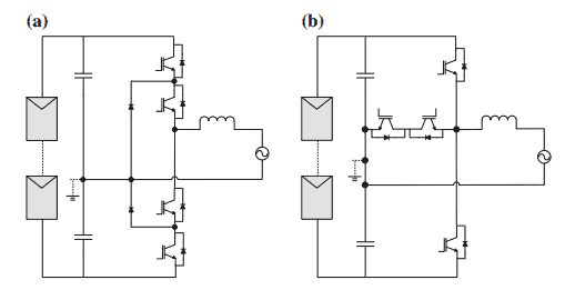
In transformerless PV inverter, the galvanic connection between the PV arrays and the grid allows leakage current to flow. The galvanic isolation can basically be categorized into DC decoupling and $\mathrm{AC}$ decoupling methods. For DC decoupling method, DC bypass switches are added on the DC side of the inverter to disconnect the PV arrays from the grid during the freewheeling period. However, the DC bypass branch, which consists of switches or diodes, is included in the conduction path as shown in Fig. 16. The output current flows through two switches and the two DC bypass branches during the conduction period. Hence, the conduction losses increase due to the increased number of semiconductors in the conduction path.

On the other hand, bypass branch can also be provided on the AC side of the inverter (i.e., AC decoupling method). This AC bypass branch functions as a freewheeling path which is completely isolated from the conduction path, as shown in Fig. 17. As a result, the output current flows through only two switches during the conduction period. In other words, topologies employing AC decoupling techniques are found to be higher in efficiency as compared to DC decoupling topologies.

One setback of galvanic isolation is that there is no way of controlling the CMV by PWM during the freewheeling period. Figures 18 and 19 show the operation modes of galvanic isolation topology which employs DC decoupling method (one DC bypass branch) during the positive half-cycle. As indicated in Fig. 18, during the conduction period, $S_1$ and $S_4$ conduct to generate the desired output voltage. At the same time, $V_{\mathrm{A}}$ is directly connected to $V_{\mathrm{DC}}$ and $V_{\mathrm{B}}$ is connected to the negative terminal $(N)$ of the DC link. Hence, the CMV becomes
$$
V_{\mathrm{CM}}=\frac{V_{\mathrm{AN}}+V_{\mathrm{BN}}}{2}=\frac{1}{2}\left(V_{\mathrm{DC}}+0\right)=\frac{V_{\mathrm{DC}}}{2}
$$

物理代写|光电技术代写Photovoltaic Technology代考|EGV2101

光电技术代考

物理代写|光电技术代写光伏技术代考|共模行为


无变压器技术提供了降低成本的高效光伏逆变器。这解释了为什么PV逆变器的趋势是向无变压器拓扑发展。为了了解无变压器拓扑结构的基本原理,本文将以单相系统为例分析共模特性。类似的共模行为分析可以扩展到三相系统,因此这里不讨论三相系统的分析。当变压器从PV逆变器上拆下时,PV阵列与电网之间形成电连接。这种电连接产生了如图12所示的漏电流路径。当逆变拓扑通过相应的脉宽调制(PWM)产生CMV时,CMV对杂散电容进行充放电。结果,泄漏电流产生,流经PV阵列和电网之间的泄漏电流路径。为了设计一个合适的无变压器光伏逆变器拓扑结构,减少泄漏电流,必须首先了解共模行为。为了研究无变压器光伏逆变器的共模特性,本文推导了一个共模模型电路,并逐级简化


对于无变压器逆变器,形成了如图$13 .$所示的谐振电路,该谐振电路包括寄生电容$\left(C_{\mathrm{PV}}\right)$,滤波电感$\left(L_1\right.$和$L_2$),漏电流$\left(I_L\right)$。在这里,功率转换器用一个具有四个终端的块来表示,以允许各种转换器拓扑的一般表示。直流侧$P$和$N$分别连接到直流链路的正极和负极;而在$\mathrm{AC}$端,终端$\mathrm{A}$和$\mathrm{B}$通过滤波电感[15]连接到单相电网

从电网的角度看,如图14所示的功率转换块可以看作是电压源,产生为由$V_{\mathrm{AN}}$和$V_{\mathrm{BN}}$组成的等效电路。显然,漏电流是$V_{\mathrm{AN}}, V_{\mathrm{BN}}$,电网电压,$L$和$C_{\mathrm{PV}}$的函数。由于电网是一个低频电压源(50或$60 \mathrm{~Hz}$),这里将忽略对共模模型的影响。因此,将电压$V_{\mathrm{AN}}$和$V_{\mathrm{BN}}$表示为$V_{\mathrm{CM}}$和$V_{\mathrm{DM}}$的函数,得到简化共模,如图15所示。

物理代写|光电技术代写光伏技术代考|电隔离


在无变压器的光伏逆变器中,光伏阵列和电网之间的电连接允许漏电流流动。电隔离基本上可以分为直流解耦和$\mathrm{AC}$解耦两种方法。直流解耦方法是在逆变器的直流侧增加直流旁路开关,使光伏阵列在自由浮动期间与电网断开。然而,如图16所示的导通路径中包含了由开关或二极管组成的直流旁路支路。输出电流在导通期间流过两个开关和两个直流旁路支路。因此,由于导通路径中半导体数量的增加,导通损耗增加

另一方面,也可以在逆变器的交流侧提供旁路支路(即交流解耦法)。如图17所示,该交流旁路支路作为与传导路径完全隔离的自由轮路径。因此,输出电流在导通期间只通过两个开关。换句话说,与直流去耦拓扑相比,采用交流去耦技术的拓扑被发现效率更高 电隔离的一个缺点是没有办法在自由浮动期间通过PWM控制CMV。图18和图19显示了采用直流解耦方法(一个直流旁路支路)的电隔离拓扑在正半周的工作方式。如图18所示,在导通期间,$S_1$和$S_4$导通产生所需输出电压。同时,$V_{\mathrm{A}}$与$V_{\mathrm{DC}}$直连,$V_{\mathrm{B}}$与直流链路的负极$(N)$相连。因此,CMV变成
$$
V_{\mathrm{CM}}=\frac{V_{\mathrm{AN}}+V_{\mathrm{BN}}}{2}=\frac{1}{2}\left(V_{\mathrm{DC}}+0\right)=\frac{V_{\mathrm{DC}}}{2}
$$

物理代写|光电技术代写Photovoltaic Technology代考 请认准statistics-lab™

统计代写请认准statistics-lab™. statistics-lab™为您的留学生涯保驾护航。

金融工程代写

金融工程是使用数学技术来解决金融问题。金融工程使用计算机科学、统计学、经济学和应用数学领域的工具和知识来解决当前的金融问题,以及设计新的和创新的金融产品。

非参数统计代写

非参数统计指的是一种统计方法,其中不假设数据来自于由少数参数决定的规定模型;这种模型的例子包括正态分布模型和线性回归模型。

广义线性模型代考

广义线性模型(GLM)归属统计学领域,是一种应用灵活的线性回归模型。该模型允许因变量的偏差分布有除了正态分布之外的其它分布。

术语 广义线性模型(GLM)通常是指给定连续和/或分类预测因素的连续响应变量的常规线性回归模型。它包括多元线性回归,以及方差分析和方差分析(仅含固定效应)。

有限元方法代写

有限元方法(FEM)是一种流行的方法,用于数值解决工程和数学建模中出现的微分方程。典型的问题领域包括结构分析、传热、流体流动、质量运输和电磁势等传统领域。

有限元是一种通用的数值方法,用于解决两个或三个空间变量的偏微分方程(即一些边界值问题)。为了解决一个问题,有限元将一个大系统细分为更小、更简单的部分,称为有限元。这是通过在空间维度上的特定空间离散化来实现的,它是通过构建对象的网格来实现的:用于求解的数值域,它有有限数量的点。边界值问题的有限元方法表述最终导致一个代数方程组。该方法在域上对未知函数进行逼近。[1] 然后将模拟这些有限元的简单方程组合成一个更大的方程系统,以模拟整个问题。然后,有限元通过变化微积分使相关的误差函数最小化来逼近一个解决方案。

tatistics-lab作为专业的留学生服务机构,多年来已为美国、英国、加拿大、澳洲等留学热门地的学生提供专业的学术服务,包括但不限于Essay代写,Assignment代写,Dissertation代写,Report代写,小组作业代写,Proposal代写,Paper代写,Presentation代写,计算机作业代写,论文修改和润色,网课代做,exam代考等等。写作范围涵盖高中,本科,研究生等海外留学全阶段,辐射金融,经济学,会计学,审计学,管理学等全球99%专业科目。写作团队既有专业英语母语作者,也有海外名校硕博留学生,每位写作老师都拥有过硬的语言能力,专业的学科背景和学术写作经验。我们承诺100%原创,100%专业,100%准时,100%满意。

随机分析代写


随机微积分是数学的一个分支,对随机过程进行操作。它允许为随机过程的积分定义一个关于随机过程的一致的积分理论。这个领域是由日本数学家伊藤清在第二次世界大战期间创建并开始的。

时间序列分析代写

随机过程,是依赖于参数的一组随机变量的全体,参数通常是时间。 随机变量是随机现象的数量表现,其时间序列是一组按照时间发生先后顺序进行排列的数据点序列。通常一组时间序列的时间间隔为一恒定值(如1秒,5分钟,12小时,7天,1年),因此时间序列可以作为离散时间数据进行分析处理。研究时间序列数据的意义在于现实中,往往需要研究某个事物其随时间发展变化的规律。这就需要通过研究该事物过去发展的历史记录,以得到其自身发展的规律。

回归分析代写

多元回归分析渐进(Multiple Regression Analysis Asymptotics)属于计量经济学领域,主要是一种数学上的统计分析方法,可以分析复杂情况下各影响因素的数学关系,在自然科学、社会和经济学等多个领域内应用广泛。

MATLAB代写

MATLAB 是一种用于技术计算的高性能语言。它将计算、可视化和编程集成在一个易于使用的环境中,其中问题和解决方案以熟悉的数学符号表示。典型用途包括:数学和计算算法开发建模、仿真和原型制作数据分析、探索和可视化科学和工程图形应用程序开发,包括图形用户界面构建MATLAB 是一个交互式系统,其基本数据元素是一个不需要维度的数组。这使您可以解决许多技术计算问题,尤其是那些具有矩阵和向量公式的问题,而只需用 C 或 Fortran 等标量非交互式语言编写程序所需的时间的一小部分。MATLAB 名称代表矩阵实验室。MATLAB 最初的编写目的是提供对由 LINPACK 和 EISPACK 项目开发的矩阵软件的轻松访问,这两个项目共同代表了矩阵计算软件的最新技术。MATLAB 经过多年的发展,得到了许多用户的投入。在大学环境中,它是数学、工程和科学入门和高级课程的标准教学工具。在工业领域,MATLAB 是高效研究、开发和分析的首选工具。MATLAB 具有一系列称为工具箱的特定于应用程序的解决方案。对于大多数 MATLAB 用户来说非常重要,工具箱允许您学习应用专业技术。工具箱是 MATLAB 函数(M 文件)的综合集合,可扩展 MATLAB 环境以解决特定类别的问题。可用工具箱的领域包括信号处理、控制系统、神经网络、模糊逻辑、小波、仿真等。

R语言代写问卷设计与分析代写
PYTHON代写回归分析与线性模型代写
MATLAB代写方差分析与试验设计代写
STATA代写机器学习/统计学习代写
SPSS代写计量经济学代写
EVIEWS代写时间序列分析代写
EXCEL代写深度学习代写
SQL代写各种数据建模与可视化代写

物理代写|光电技术代写Photovoltaic Technology代考|ELC220

如果你也在 怎样代写光电技术Photovoltaic Technology这个学科遇到相关的难题,请随时右上角联系我们的24/7代写客服。

光伏材料和装置将太阳光转化为电能。一个单一的光伏设备被称为电池。

statistics-lab™ 为您的留学生涯保驾护航 在代写光电技术Photovoltaic Technology方面已经树立了自己的口碑, 保证靠谱, 高质且原创的统计Statistics代写服务。我们的专家在代写光电技术Photovoltaic Technology代写方面经验极为丰富,各种代写光电技术Photovoltaic Technology相关的作业也就用不着说。

我们提供的光电技术Photovoltaic Technology及其相关学科的代写,服务范围广, 其中包括但不限于:

  • Statistical Inference 统计推断
  • Statistical Computing 统计计算
  • Advanced Probability Theory 高等概率论
  • Advanced Mathematical Statistics 高等数理统计学
  • (Generalized) Linear Models 广义线性模型
  • Statistical Machine Learning 统计机器学习
  • Longitudinal Data Analysis 纵向数据分析
  • Foundations of Data Science 数据科学基础
物理代写|光电技术代写Photovoltaic Technology代考|ELC220

物理代写|光电技术代写Photovoltaic Technology代考|Module Configuration

Module inverter is also known as micro-inverter. In contrast to centralized configuration, each micro-inverter is attached to a single PV module, as shown in Fig. 1a. Because of the “one PV module one inverter concept,” the mismatch loss between the PV modules is completely eliminated, leading to higher energy yields. With module configuration, expansion and installation become an easy task. Micro-inverter certainly allows for a very high degree of flexibility, but it comes at an expense of higher upfront costs and greater service requirements. A large number of inverters are required for large-scale application. DC-DC converter is usually included in micro-inverter to boost the low voltage of the PV module to meet the grid requirement. High voltage amplification may shrink overall efficiency and increase price per watt. Although micro-inverters are typically used in low-power application, large-scale PV plant with micro-inverters is emerging. As shown in Fig. 5, Enphase (ENPH) installed a $2 \mathrm{MW}$ solar project at Ontario, Canada’s Vine Fresh Produce, with 9000 Enphase ${ }^{\circledR}$ M215 micro-inverters [12].
Micro-inverters usually come with longer warranty up to 25 years, thanks to their effort to extend the lifespan of the capacitors. The first approach is to eliminate the use of electrolytic capacitors by Enecsys [13]. Enecsys $240 \mathrm{~W}$ micro-inverters are the first micro-inverters without electrolytic capacitors to achieve higher reliability. The micro-inverter configuration is shown in Fig. 6, which includes a DC$\mathrm{DC}$ boost converter and a $\mathrm{DC}-\mathrm{AC}$ inverter (universal converter). The $\mathrm{DC}-\mathrm{DC}$ converter is made up of a resonant $\mathrm{H}$-bridge, a high-frequency (HF) transformer, and a bridge rectifier. With buck, boost and buck-boost capability, the universal converter can operate with a wide range of input voltage, improving the power quality and the efficiency [10]. Without the use of electrolytic capacitors, the inverter has an operating life expectancy of greater than 25 years, matching that of solar PV modules. The second approach is the use of interleaved flyback converter. The Enphase micro-inverter configuration is shown in Fig. 7 [14]. The flyback converter is connected in parallel, and modulated with interleaved PWM. Compared with the conventional flyback converter, interleaved topology requires smaller filter capacitors and smaller HF transformer, which offers higher power capability with greater life expectancy.

物理代写|光电技术代写Photovoltaic Technology代考|String Configuration

In string configuration, each inverter is attached to only one PV string, avoiding the use of blocking diode as shown in Fig. 1b. String inverter combines the advantages of simple structure central inverter and high-energy-yield micro-inverter. Higher energy yield is achieved with MPPT operating at string level, thereby reducing the mismatch loss between the PV modules as compared to centralized configuration. Since the configuration is made up of one PV string per inverter, the string inverter is usually designed for low power application, typically for residential rooftop application.

In the past, U.S. regulations dictated that all electrical systems must be grounded. For grounded PV system, galvanic isolation must be provided in order to avoid the leakage current. Galvanic isolation can be provided via HF transformer on the DC side or via LF transformer on the $\mathrm{AC}$ side as shown in Fig. 8 [15]. Besides isolation, transformer steps up the inpul voltage, which provides a wide range of input voltage. However, the transformer is bulky, heavy, and expensive. Even though significant size and weight reduction can be achieved with HF transformer, the use of transformer still reduces the efficiency of the entire PV system.

Since 2005, the National Electric Code update for allowing ungrounded system opens a huge market for transformerless technology. There are numerous types of string inverters available in the market, and only several will be covered here as shown in Fig. 9. The simplest transformerless string inverter is the full-bridge topology as shown in Fig. 9a. The full-bridge topology is modulated by bipolar PWM in order to generate constant CMV, to eliminate the leakage current. Nonetheless, the two-level bipolar PWM doubles the voltage stress and current ripples across the filter inductors, reducing the efficiency of the PV system.

To achieve high efficiency, various inverter manufacturers have developed different circuit configuration with three-level unipolar PWM. The Sunway HERIC topology (Fig. 9b) [16] and the SMA H5 topology (Fig. 9c) [17] introduce DC decoupling and $\mathrm{AC}$ decoupling methods, respectively, to disconnect the PV string from the grid. The former provides lower conduction loss due to reduced semiconductors in the conduction path. However, galvanic isolation alone cannot completely eliminate the leakage current due to the influence of switches’ junction capacitances and parasitic parameters. Therefore, CMV clamping method is proposed in the H6 topology by Ingeteam [18] to completely eliminate the leakage current as shown in Fig. 9c. Two clamping diodes are added in additional to the DC decoupling switches to completely clamp the freewheeling path to half of the input voltage, $V_{\mathrm{DC}} / 2$

物理代写|光电技术代写Photovoltaic Technology代考|ELC220

光电技术代考

物理代写|光电技术代写光伏技术代考|模块配置


模块逆变器又称微逆变器。与集中式配置相比,每个微型逆变器都连接到单个光伏模块上,如图1a所示。由于“一个光伏模块一个逆变器的概念”,光伏模块之间的失配损失完全消除,导致更高的发电量。通过模块配置,扩展和安装变得很容易。微逆变器当然允许非常高的灵活性,但它以更高的前期成本和更大的服务要求为代价。大规模应用需要大量的逆变器。微逆变器中通常包含DC-DC变换器,对光伏组件的低电压进行升压,以满足电网的要求。高压放大可能会降低整体效率,提高每瓦价格。虽然微逆变器通常用于低功率应用,但采用微逆变器的大型光伏电站正在出现。如图5所示,Enphase (ENPH)在加拿大安大略省的Vine Fresh Produce安装了$2 \mathrm{MW}$太阳能项目,使用9000个Enphase ${ }^{\circledR}$ M215微逆变器[12]。由于微逆变器努力延长电容器的寿命,它们通常具有较长的质保期,可达25年。第一种方法是通过Enecsys[13]消除电解电容器的使用。Enecsys $240 \mathrm{~W}$微逆变器是第一个没有电解电容的微逆变器,以实现更高的可靠性。微逆变器配置如图6所示,其中包括一个直流$\mathrm{DC}$升压变换器和一个$\mathrm{DC}-\mathrm{AC}$逆变器(通用变换器)。$\mathrm{DC}-\mathrm{DC}$转换器由一个谐振$\mathrm{H}$桥、一个高频(HF)变压器和一个桥式整流器组成。该通用变换器具有降压、升压和降压升压能力,可在较大的输入电压范围内工作,提高了电能质量和效率[10]。在不使用电解电容器的情况下,逆变器的工作寿命超过25年,与太阳能光伏组件相当。第二种方法是使用交错反激变换器。恩相微逆变器配置如图7[14]所示。反激式变换器并联连接,采用交错PWM调制。与传统的反激变换器相比,交错拓扑结构需要更小的滤波电容和更小的高频变压器,从而提供更高的功率能力和更长的预期寿命

物理代写|光电技术代写光伏技术代考|字符串配置

. String Configuration .物理代写|光电技术代写光伏技术代考|


在串配置中,每个逆变器只连接到一个PV串,避免使用阻塞二极管,如图1b所示。串逆变器结合了结构简单的中心逆变器和高能产率微型逆变器的优点。MPPT在串级运行时可获得更高的能量产出,因此与集中配置相比,减少了光伏组件之间的失配损失。由于配置由每个逆变器一个PV串组成,串逆变器通常设计为低功率应用,通常用于住宅屋顶应用


在过去,美国规定所有的电气系统必须接地。对于接地的光伏系统,必须提供电隔离,以避免泄漏电流。电隔离可以通过直流侧的高频变压器或通过$\mathrm{AC}$侧的低频变压器提供,如图8[15]所示。除了隔离,变压器逐步增加输入电压,这提供了一个广泛的输入电压范围。然而,变压器是笨重的,沉重的,昂贵的。尽管使用高频变压器可以实现显著的尺寸和重量减小,但变压器的使用仍然降低了整个PV系统的效率


自2005年以来,国家电气法规的更新允许不接地系统为无变压器技术打开了一个巨大的市场。市场上有许多类型的串逆变器,这里只介绍几种,如图9所示。最简单的无变压器串逆变器是全桥拓扑如图9a所示。全桥拓扑由双极PWM调制,以产生恒定的CMV,以消除漏电流。尽管如此,两电平双极PWM使电压应力和电流波纹在滤波器电感上加倍,降低了PV系统的效率


为了达到高效率,各种逆变器制造商开发了不同的三电平单极PWM电路配置。Sunway HERIC拓扑(图9b)[16]和SMA H5拓扑(图9c)[17]分别引入了直流解耦和$\mathrm{AC}$解耦方法,将PV串与电网断开。前者由于在传导路径中减少了半导体,从而提供了较低的传导损耗。然而,由于开关结电容和寄生参数的影响,单纯的电隔离并不能完全消除漏电流。因此,Ingeteam[18]在H6拓扑中提出了CMV夹紧方法,以完全消除泄漏电流,如图9c所示。除了直流去耦开关之外,还添加了两个夹紧二极管,以完全夹紧自由轮路径到输入电压的一半$V_{\mathrm{DC}} / 2$

物理代写|光电技术代写Photovoltaic Technology代考 请认准statistics-lab™

统计代写请认准statistics-lab™. statistics-lab™为您的留学生涯保驾护航。

金融工程代写

金融工程是使用数学技术来解决金融问题。金融工程使用计算机科学、统计学、经济学和应用数学领域的工具和知识来解决当前的金融问题,以及设计新的和创新的金融产品。

非参数统计代写

非参数统计指的是一种统计方法,其中不假设数据来自于由少数参数决定的规定模型;这种模型的例子包括正态分布模型和线性回归模型。

广义线性模型代考

广义线性模型(GLM)归属统计学领域,是一种应用灵活的线性回归模型。该模型允许因变量的偏差分布有除了正态分布之外的其它分布。

术语 广义线性模型(GLM)通常是指给定连续和/或分类预测因素的连续响应变量的常规线性回归模型。它包括多元线性回归,以及方差分析和方差分析(仅含固定效应)。

有限元方法代写

有限元方法(FEM)是一种流行的方法,用于数值解决工程和数学建模中出现的微分方程。典型的问题领域包括结构分析、传热、流体流动、质量运输和电磁势等传统领域。

有限元是一种通用的数值方法,用于解决两个或三个空间变量的偏微分方程(即一些边界值问题)。为了解决一个问题,有限元将一个大系统细分为更小、更简单的部分,称为有限元。这是通过在空间维度上的特定空间离散化来实现的,它是通过构建对象的网格来实现的:用于求解的数值域,它有有限数量的点。边界值问题的有限元方法表述最终导致一个代数方程组。该方法在域上对未知函数进行逼近。[1] 然后将模拟这些有限元的简单方程组合成一个更大的方程系统,以模拟整个问题。然后,有限元通过变化微积分使相关的误差函数最小化来逼近一个解决方案。

tatistics-lab作为专业的留学生服务机构,多年来已为美国、英国、加拿大、澳洲等留学热门地的学生提供专业的学术服务,包括但不限于Essay代写,Assignment代写,Dissertation代写,Report代写,小组作业代写,Proposal代写,Paper代写,Presentation代写,计算机作业代写,论文修改和润色,网课代做,exam代考等等。写作范围涵盖高中,本科,研究生等海外留学全阶段,辐射金融,经济学,会计学,审计学,管理学等全球99%专业科目。写作团队既有专业英语母语作者,也有海外名校硕博留学生,每位写作老师都拥有过硬的语言能力,专业的学科背景和学术写作经验。我们承诺100%原创,100%专业,100%准时,100%满意。

随机分析代写


随机微积分是数学的一个分支,对随机过程进行操作。它允许为随机过程的积分定义一个关于随机过程的一致的积分理论。这个领域是由日本数学家伊藤清在第二次世界大战期间创建并开始的。

时间序列分析代写

随机过程,是依赖于参数的一组随机变量的全体,参数通常是时间。 随机变量是随机现象的数量表现,其时间序列是一组按照时间发生先后顺序进行排列的数据点序列。通常一组时间序列的时间间隔为一恒定值(如1秒,5分钟,12小时,7天,1年),因此时间序列可以作为离散时间数据进行分析处理。研究时间序列数据的意义在于现实中,往往需要研究某个事物其随时间发展变化的规律。这就需要通过研究该事物过去发展的历史记录,以得到其自身发展的规律。

回归分析代写

多元回归分析渐进(Multiple Regression Analysis Asymptotics)属于计量经济学领域,主要是一种数学上的统计分析方法,可以分析复杂情况下各影响因素的数学关系,在自然科学、社会和经济学等多个领域内应用广泛。

MATLAB代写

MATLAB 是一种用于技术计算的高性能语言。它将计算、可视化和编程集成在一个易于使用的环境中,其中问题和解决方案以熟悉的数学符号表示。典型用途包括:数学和计算算法开发建模、仿真和原型制作数据分析、探索和可视化科学和工程图形应用程序开发,包括图形用户界面构建MATLAB 是一个交互式系统,其基本数据元素是一个不需要维度的数组。这使您可以解决许多技术计算问题,尤其是那些具有矩阵和向量公式的问题,而只需用 C 或 Fortran 等标量非交互式语言编写程序所需的时间的一小部分。MATLAB 名称代表矩阵实验室。MATLAB 最初的编写目的是提供对由 LINPACK 和 EISPACK 项目开发的矩阵软件的轻松访问,这两个项目共同代表了矩阵计算软件的最新技术。MATLAB 经过多年的发展,得到了许多用户的投入。在大学环境中,它是数学、工程和科学入门和高级课程的标准教学工具。在工业领域,MATLAB 是高效研究、开发和分析的首选工具。MATLAB 具有一系列称为工具箱的特定于应用程序的解决方案。对于大多数 MATLAB 用户来说非常重要,工具箱允许您学习应用专业技术。工具箱是 MATLAB 函数(M 文件)的综合集合,可扩展 MATLAB 环境以解决特定类别的问题。可用工具箱的领域包括信号处理、控制系统、神经网络、模糊逻辑、小波、仿真等。

R语言代写问卷设计与分析代写
PYTHON代写回归分析与线性模型代写
MATLAB代写方差分析与试验设计代写
STATA代写机器学习/统计学习代写
SPSS代写计量经济学代写
EVIEWS代写时间序列分析代写
EXCEL代写深度学习代写
SQL代写各种数据建模与可视化代写

物理代写|光电技术代写Photovoltaic Technology代考|ECE6456

如果你也在 怎样代写光电技术Photovoltaic Technology这个学科遇到相关的难题,请随时右上角联系我们的24/7代写客服。

光伏材料和装置将太阳光转化为电能。一个单一的光伏设备被称为电池。

statistics-lab™ 为您的留学生涯保驾护航 在代写光电技术Photovoltaic Technology方面已经树立了自己的口碑, 保证靠谱, 高质且原创的统计Statistics代写服务。我们的专家在代写光电技术Photovoltaic Technology代写方面经验极为丰富,各种代写光电技术Photovoltaic Technology相关的作业也就用不着说。

我们提供的光电技术Photovoltaic Technology及其相关学科的代写,服务范围广, 其中包括但不限于:

  • Statistical Inference 统计推断
  • Statistical Computing 统计计算
  • Advanced Probability Theory 高等概率论
  • Advanced Mathematical Statistics 高等数理统计学
  • (Generalized) Linear Models 广义线性模型
  • Statistical Machine Learning 统计机器学习
  • Longitudinal Data Analysis 纵向数据分析
  • Foundations of Data Science 数据科学基础
物理代写|光电技术代写Photovoltaic Technology代考|ECE6456

物理代写|光电技术代写Photovoltaic Technology代考|Organization of the Book

For grid integration of PV system, either compact high-frequency transformer or bulky low frequency transformer is employed in the dc- or ac-side of the PV inverter, respectively, to step up the low output voltage of the PV modules to the grid voltage. Galvanic isolation is provided and the safety is assured with the use of transformer. Because of the high cost and significant loss of the transformer, the PV inverter becomes expensive and poor efficient. To mitigate these problems, the transformer is removed from the PV inverter. The transformerless PV inverter is smaller, cheaper, and higher in efficiency. Various transformerless PV inverter topologies, with different circuit configuration and modulation techniques, have been developed recently. The operating principle and the converter structure are evaluated in Chap. 2. It is expected that the transformerless PV inverter would have great potential for future renewable generation and smart micro grid applications.
Tracking the maximum power of the PV arrays at real time is very important to increase the whole system performance. In the past decades, there are a large number of maximum power point tracking (MPPT) methods have been proposed for PV system, such as constant-voltage tracing method (CVT), perturbation, and observation method (P\&O), incremental conductance method (INC), curve fitting method, look-up table method, and so on. Actually, these conventional methods can track the MPP. But these methods have some drawbacks, like oscillation, miscalculation, poor accuracy, unimodal $P-U$ curves only. To overcome the limitation of these methods, some advanced MPPT methods are introduced in Chap. 3. In Chap. 4, the criteria for assessing the performance of MPPT methods are defined followed by a complete description and discussion of both techniques designed for uniform environmental conditions and those designed for nonuniform environmental conditions.

Most of the conventional MPPT algorithms are incapable to detect global peak power point with the presence of several local peaks. A hybrid particle swarm optimization and artificial neural network (PSO-ANN) algorithm is proposed in Chap. 5 to detect the global peak power. The performance of the proposed algorithm is compared with that of the standard PSO algorithm. The proposed algorithm is tested and verified by hardware experiment. The simulation and the experimental results are compared and discussed in the Chapter.

物理代写|光电技术代写Photovoltaic Technology代考|Centralized Configuration

When a large number of PV modules are interfaced with a single three-phase inverter as shown in Fig. 1d, this configuration is termed as central inverter. The PV modules are connected into series (called strings) to achieve sufficiently high voltage. These PV strings are then made parallel (called arrays) to reach high power level. A blocking diode is connected in series with each PV string branch to avoid reverse current. Central inverter is widely installed in large-scale PV plant. Because of the centralized configuration (with single set of sensors, control platform, and monitoring unit), the central inverter becomes cost-effective for large-scale application. However, the simple configuration comes at a cost of high-level mismatch loss between the PV modules owing to the utilization of a common maximum power point tracking (MPPT) for the entire PV arrays. The power generation loss becomes apparent during the inverter outages. The expansion of the power plant is also difficult to be realized at centralized level.

The conventional central inverter topology is a two-level three-phase full-bridge converter, as indicated in Fig. 2. It is called two-level because it can apply only two voltage levels: the DC supply voltage and the reverse of that voltage. The two-level inverter consists of DC-link capacitors, full-bridge inverter (6 IGBTs) and filters. The central inverter is connected to medium voltage network via a transformer to step up the voltage from LV (e.g., $400 \mathrm{~V}$ ) to MV level (e.g., $11 \mathrm{kV}$ ). To meet higher power requirement, the PV inverter industry, such as ABB PVS800 central inverter [9], introduces a parallel connection directly to the $\mathrm{AC}$ side, enabling power to be fed to the medium voltage network via a single transformer as illustrated in Fig. 3. This avoids the need of individual transformer for each central inverter, reducing the cost and space. Nevertheless, in systems where the DC side needs to he grounded, a separate transformer must he employed for galvanic isolation.

The demand of higher power central inverter (MW range) has been continuously increasing with the emerging large-scale PV plant. Although advanced semiconductors with higher nominal voltage and current capability are available, they are very relatively more expensive with high loss. On the other hand, the high-power central inverter is made possible with multilevel configuration. Because of its reduced voltage derivatives $(\mathrm{d} v / \mathrm{d} t)$ and higher voltage operating capability, the multilevel converter becomes attractive for high power application. The multilevel converter generates increased level at output phase voltage, which leads to higher power quality and reduced switching loss. Nonetheless, the high power quality requires higher complexity of circuit configuration and the corresponding control, which leads to higher initial cost. The three-phase three-level neutral point clamped (3L-NPC) converter and the T-type (3L-T) converter are two widely used converter as shown in Fig. 4 [10]. The NPC and T-type converter modules have been commercialized by several manufacturers such as Semikron, Infineon and Fuji [11].

物理代写|光电技术代写Photovoltaic Technology代考|ECE6456

光电技术代考

物理代写|光电技术代写光伏科技代考|书的组织


对于光伏系统的电网集成,在光伏逆变器的直流侧或交流侧分别使用小型高频变压器或大型低频变压器,将光伏组件的低输出电压提升到电网电压。使用变压器可实现电隔离,保证安全。由于变压器的高成本和显著损耗,光伏逆变器变得昂贵和效率低下。为了缓解这些问题,变压器被从PV逆变器中移除。无变压器的光伏逆变器体积更小,成本更低,效率更高。各种无变压器的光伏逆变器拓扑,具有不同的电路配置和调制技术,最近已经开发出来。第二章评价了该转换器的工作原理和结构。预计无变压器光伏逆变器在未来可再生能源发电和智能微电网应用中具有巨大潜力。实时跟踪光伏阵列的最大功率对提高整个系统的性能非常重要。在过去的几十年里,针对光伏系统提出了大量的最大功率点跟踪(MPPT)方法,如恒电压跟踪法(CVT)、摄动观测法(P&O)、增量电导法(INC)、曲线拟合法、查表法等。实际上,这些传统方法可以跟踪MPP。但这些方法存在一些缺点,如振荡、计算错误、精度差、仅$P-U$曲线为单峰曲线。为了克服这些方法的局限性,第三章介绍了一些先进的MPPT方法。在第4章中,定义了评估MPPT方法性能的标准,随后对适用于均匀环境条件和适用于非均匀环境条件的技术进行了完整的描述和讨论


在存在多个局部峰值的情况下,大多数传统的MPPT算法都无法检测到全局峰值功率点。第五章提出了一种混合粒子群优化和人工神经网络(PSO-ANN)算法来检测全局峰值功率。并与标准粒子群算法的性能进行了比较。通过硬件实验验证了算法的正确性。本章对模拟结果和实验结果进行了比较和讨论

物理代写|光电技术代写光伏技术代考|集中配置


如图1d所示,当大量光伏模块与单个三相逆变器连接时,这种配置称为中心逆变器。PV模块连接成串联(称为串)以获得足够高的电压。这些PV串然后被并联(称为阵列)以达到高功率水平。阻塞二极管与每个PV串支路串联,以避免反向电流。中央逆变器广泛安装在大型光伏电站中。由于集中配置(单组传感器、控制平台和监控单元),中央逆变器在大规模应用中具有较高的性价比。然而,由于对整个光伏阵列使用了通用的最大功率点跟踪(MPPT),这种简单的配置以光伏模块之间的高级别失配损失为代价。在逆变器停机期间,发电损失变得明显。发电厂的扩建也很难在集中的层面上实现


传统的中心逆变器拓扑是一个两电平三相全桥变换器,如图2所示。它被称为两电平,因为它只能应用两个电压电平:直流电源电压和该电压的反向电压。两电平逆变器由直流连接电容、全桥逆变器(6个igbt)和滤波器组成。中央逆变器通过变压器连接到中压网络,将电压从LV(如$400 \mathrm{~V}$)升到MV(如$11 \mathrm{kV}$)。为了满足更高的功率要求,光伏逆变器行业,如ABB PVS800中央逆变器[9],引入了直接到$\mathrm{AC}$侧的并联连接,使功率通过单个变压器馈电到中压网络,如图3所示。这避免了每个中央逆变器需要单独的变压器,减少了成本和空间。然而,在直流侧需要接地的系统中,必须使用单独的变压器进行电隔离


随着大规模光伏电站的出现,对功率更高的中央逆变器(MW范围)的需求不断增加。虽然先进的半导体具有较高的标称电压和电流能力,但它们相对昂贵,损耗高。另一方面,大功率中央逆变器通过多级配置成为可能。由于其降低的电压导数$(\mathrm{d} v / \mathrm{d} t)$和更高的电压操作能力,多电平转换器成为高功率应用的吸引力。多电平变换器在输出相电压时产生更高的电平,从而提高电能质量,减少开关损耗。然而,高功率质量对电路配置和相应控制的要求较高,导致初始成本较高。三相三电平中性点箝位(3L-NPC)转换器和t型(3L-T)转换器是两种广泛应用的转换器,如图4[10]所示。NPC和t型转换器模块已被几家制造商商业化,如赛米龙,英飞凌和富士[11]

物理代写|光电技术代写Photovoltaic Technology代考 请认准statistics-lab™

统计代写请认准statistics-lab™. statistics-lab™为您的留学生涯保驾护航。

金融工程代写

金融工程是使用数学技术来解决金融问题。金融工程使用计算机科学、统计学、经济学和应用数学领域的工具和知识来解决当前的金融问题,以及设计新的和创新的金融产品。

非参数统计代写

非参数统计指的是一种统计方法,其中不假设数据来自于由少数参数决定的规定模型;这种模型的例子包括正态分布模型和线性回归模型。

广义线性模型代考

广义线性模型(GLM)归属统计学领域,是一种应用灵活的线性回归模型。该模型允许因变量的偏差分布有除了正态分布之外的其它分布。

术语 广义线性模型(GLM)通常是指给定连续和/或分类预测因素的连续响应变量的常规线性回归模型。它包括多元线性回归,以及方差分析和方差分析(仅含固定效应)。

有限元方法代写

有限元方法(FEM)是一种流行的方法,用于数值解决工程和数学建模中出现的微分方程。典型的问题领域包括结构分析、传热、流体流动、质量运输和电磁势等传统领域。

有限元是一种通用的数值方法,用于解决两个或三个空间变量的偏微分方程(即一些边界值问题)。为了解决一个问题,有限元将一个大系统细分为更小、更简单的部分,称为有限元。这是通过在空间维度上的特定空间离散化来实现的,它是通过构建对象的网格来实现的:用于求解的数值域,它有有限数量的点。边界值问题的有限元方法表述最终导致一个代数方程组。该方法在域上对未知函数进行逼近。[1] 然后将模拟这些有限元的简单方程组合成一个更大的方程系统,以模拟整个问题。然后,有限元通过变化微积分使相关的误差函数最小化来逼近一个解决方案。

tatistics-lab作为专业的留学生服务机构,多年来已为美国、英国、加拿大、澳洲等留学热门地的学生提供专业的学术服务,包括但不限于Essay代写,Assignment代写,Dissertation代写,Report代写,小组作业代写,Proposal代写,Paper代写,Presentation代写,计算机作业代写,论文修改和润色,网课代做,exam代考等等。写作范围涵盖高中,本科,研究生等海外留学全阶段,辐射金融,经济学,会计学,审计学,管理学等全球99%专业科目。写作团队既有专业英语母语作者,也有海外名校硕博留学生,每位写作老师都拥有过硬的语言能力,专业的学科背景和学术写作经验。我们承诺100%原创,100%专业,100%准时,100%满意。

随机分析代写


随机微积分是数学的一个分支,对随机过程进行操作。它允许为随机过程的积分定义一个关于随机过程的一致的积分理论。这个领域是由日本数学家伊藤清在第二次世界大战期间创建并开始的。

时间序列分析代写

随机过程,是依赖于参数的一组随机变量的全体,参数通常是时间。 随机变量是随机现象的数量表现,其时间序列是一组按照时间发生先后顺序进行排列的数据点序列。通常一组时间序列的时间间隔为一恒定值(如1秒,5分钟,12小时,7天,1年),因此时间序列可以作为离散时间数据进行分析处理。研究时间序列数据的意义在于现实中,往往需要研究某个事物其随时间发展变化的规律。这就需要通过研究该事物过去发展的历史记录,以得到其自身发展的规律。

回归分析代写

多元回归分析渐进(Multiple Regression Analysis Asymptotics)属于计量经济学领域,主要是一种数学上的统计分析方法,可以分析复杂情况下各影响因素的数学关系,在自然科学、社会和经济学等多个领域内应用广泛。

MATLAB代写

MATLAB 是一种用于技术计算的高性能语言。它将计算、可视化和编程集成在一个易于使用的环境中,其中问题和解决方案以熟悉的数学符号表示。典型用途包括:数学和计算算法开发建模、仿真和原型制作数据分析、探索和可视化科学和工程图形应用程序开发,包括图形用户界面构建MATLAB 是一个交互式系统,其基本数据元素是一个不需要维度的数组。这使您可以解决许多技术计算问题,尤其是那些具有矩阵和向量公式的问题,而只需用 C 或 Fortran 等标量非交互式语言编写程序所需的时间的一小部分。MATLAB 名称代表矩阵实验室。MATLAB 最初的编写目的是提供对由 LINPACK 和 EISPACK 项目开发的矩阵软件的轻松访问,这两个项目共同代表了矩阵计算软件的最新技术。MATLAB 经过多年的发展,得到了许多用户的投入。在大学环境中,它是数学、工程和科学入门和高级课程的标准教学工具。在工业领域,MATLAB 是高效研究、开发和分析的首选工具。MATLAB 具有一系列称为工具箱的特定于应用程序的解决方案。对于大多数 MATLAB 用户来说非常重要,工具箱允许您学习应用专业技术。工具箱是 MATLAB 函数(M 文件)的综合集合,可扩展 MATLAB 环境以解决特定类别的问题。可用工具箱的领域包括信号处理、控制系统、神经网络、模糊逻辑、小波、仿真等。

R语言代写问卷设计与分析代写
PYTHON代写回归分析与线性模型代写
MATLAB代写方差分析与试验设计代写
STATA代写机器学习/统计学习代写
SPSS代写计量经济学代写
EVIEWS代写时间序列分析代写
EXCEL代写深度学习代写
SQL代写各种数据建模与可视化代写